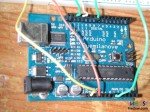
Good! Now first version of a quick traffic lights: power is in your fingers!
We'll change digital pins (both on circuit and sofware) from 9, 10 and 11 to 8, 12 and 13; no specific reason, just to use other pins (see picture beside).
Leave the rest untouched.
And a possible code is:
const int analogInPin = A0;  // Analog input the pot is attached to

const int OutPin8 = 8;
const int OutPin12 = 12;
const int OutPin13 = 13;

int sensorValue = 0;        // value read from the pot
int outputValue = 0;        // value output
void setup() {
  pinMode(OutPin8, OUTPUT);
  pinMode(OutPin12, OUTPUT);
  pinMode(OutPin13, OUTPUT);
}

void loop() {
  // read the analog in value:
  sensorValue = analogRead(analogInPin); // min 0 max 1023

  if (sensorValue <= 400)
  { // Red on
    digitalWrite(OutPin8, LOW);
    digitalWrite(OutPin12, LOW);
    digitalWrite(OutPin13, HIGH);
  }
  else if (sensorValue >= 401 && outputValue <= 600)
       { // Yellow on
         digitalWrite(OutPin8, LOW);
         digitalWrite(OutPin12, HIGH);
         digitalWrite(OutPin13, LOW);
       }
       else
         { // Green on
           digitalWrite(OutPin8, HIGH);
           digitalWrite(OutPin12, LOW);
           digitalWrite(OutPin13, LOW);
         }
 }
What's the result? Here it is!
Note that when Green is on, Arduino's Red on board is too; this is because on digital pin 13 we have now connected 2 LEDs: ours and the default, so that we could use only this last and put the green instead of our red.