We're talking again of the monostable configuration: the timing calculation is the matter.
First of that we'd do better to have a closer look at the timing aspects.
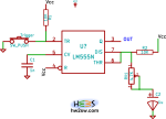
As clearly seen the couple resistor-capacitor in input to pin 6 fixes the amount of time during which the output is high.
The simple multiplication returns a time dimension, but it must be corrected by a factor (a constant) to be determined.
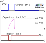
To do this please refer to the above image: again we have a temporal diagram with a hypothetical flow of signals involved, for a non-retriggerable monostable.
Now the time is the main matter: how to determine a correct value for the tON at output?
Well, the calculation is simple because the classical formula of charging for capacitor is known.
Without to much details, the basic describing equation is a simple first order linear differential equation, with constant coefficients: the solution has the nature of an exponential, power of the number of Neper e.
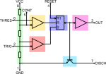
Before analyzing the diagram we must remember the behavior of NE555, in special way the boundaries at which the Set and Reset conditions can be imposed, thanks to the external components.
Basically we have:
- Set imposed when voltage at pin 2 goes down 1/3 Vcc (positive power supply);
- Reset imposed when voltage at pin 6 goes beyond 2/3 Vcc.
All this is valid remembering that Set condition has predominance, so that when the listed conditions are simultaneously satisfied (we called it the not-allowed state) then Set overwrites Reset, giving high output.


For the analysis let's start with the capacitor totally discharged: we know that by putting pin2 at V < 1/3 Vcc then we get S=1; this will impose the output high independently from the R value.
Suppose we do this; now the internal bjt - pin 7 - is interdicted, it doesn't short the collector to the emitter tied to ground, so the collector has voltage near Vcc and the capacitor starts to charge.
Well... when voltage on top of cap reaches 2/3 Vcc then we get the cap discharging through the internal bjt, now in saturation with collector almost at ground.
After that a new right trigger input makes the one-shot cycle repeat again with the same amount of time, dependent by the external R and C.
Calculation of time is very easy.
From the link above we get that the general solution formula, which we must modify for our goals: .
So from the last formula we have the t becomes the new value to find, implying that in some way we know the Vcap(t) value, otherwise we'd have an equation with two unknown values: impossible to solve.
Indeed the Vcap(t) is simple, because it starts form 0 and goes not beyond 2/3 Vcc; and that's it!
We have Vcap(t-final) - Vcap(t-initial) = 2/3 Vcc - 0 = 2/3 Vcc.
Finally .
With few passages we have the final formula for monostable multi-vibrator made with NE555:
.