Skip to content

Making DMM
Making DMM

In this third and last article of this series we will add two libraries in our Lazarus project and the event handling.
The compiled project can be found at TrustFm website.
We are going to use the synaser library (part of synapse) for the serial communication and the PlotPanel in order to plot our real time graph.
For synaser we are going to add only the "synaser.pas" file into our project.

For the PlotPanel we need to add the "plotpanel.pas" file into our project.

More informations for synaser can be found here and for PlotPanel here

...continue reading "Designing the software data logger for MASTECH MS8229 part2"
hole hack 3
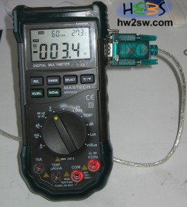
MASTECH MS8229

We have seen in this article how to hack fiscally our multimeter.
Now we have to start building our software in order to parse the 14 byte hexadecimal string into something more human.
The knowledge of bitwise operations is highly recommended and specially the masking technique (bitwise AND).
It is now time to start !
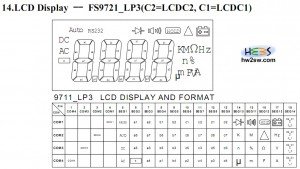
From theĀ FS9721-LP3 documentation we clearly see that we get as response from the device a 14 byte code.
Each byte of this code has this structure NNNNXXXX where NNNN is the number of the segment of the table.
The reported table below has 14 segments (seg1-14).

The XXXX part reveals which bits of the NNNN segment are active (1 = true) or not (0= false).
We immediately understand that a correct code should be 1X 2X 3X 4X 5X 6X 7X 8X 9X AX BX CX DX EX since all the segment columns of the table should be filled.

Mastech MS8229 LCD Decoding table

Time for an example. If the first byte of the 14-byte code is 17 (in hex) means that we are talking about the segment 1 (which is correct) and the settings for this first segment are 7 (in hex) or 0111 in binary.
From the table we discover that RS232,AUTO and DC should be on and AC off.

...continue reading "Designing the software data logger for MASTECH MS8229"

Circular Menus Redux

Seems like the old circular menu class is now incompatible with the new Arduino 1.0 GUI version.
Rober Wagner from the arduino forum described the incompatibility. He also sent to us an email and we thank him for the contribution.
The circular menu seems to interest a lot of people so we decided to "port" the circular menu class into the new Arduino 1.0 GUI.
We will try to describe the class in the future.
Now before starting have a look at the documentation of the "old circular menu".
As always you have to construct the three button configuration on your breadboard.
The down button is on digital port 7 the right button on digital port 6 and the enter button at digital port 5.
In order to find out how to connect buttons on your arduino please read the "arduino and memory how to" tutorial.

...continue reading "Circular menu in arduino redux"

Creating menus for embedded devices is often challenging.
Usually you have very little resources and complicated menus can not be an option.

More buttons offer more possibilities but also a more complex user interface and more hardware resources.

Why more hardware resources?

Going back at the "arduino and memory how to" article we have used the button change example.
One button use one pin as input pin from our arduino processor.
So for more buttons you need more pins.

There are methods that you can "bypass" this problem as we will see in next articles but anyway more buttons = more cost.

...continue reading "Circular menu in arduino"