Skip to content

Astable-basic-circuit
Astable - basic circuit

As promised last time we're here completing the multi-vibrator astable cycle with a test on breadboard.
Here beside a from-top photo of a base pull-up set (i.e. resistors go from positive supply to bases. Pull-downs start from ground).

Very quickly: some screenshots from oscilloscope will reveal what indeed we've discovered with an on-chart look.

The present post doesn't cover deep technical details but tends to give a consistent view about what happens with a real astable circuit.
Jelly-beans parts are used so that it's easy and cheap for everybody to replicate it in a quick.

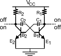
In this case the bjts are two npn BC548C, very common low power amplifying transistors here used in switch mode; then two 1k resistors (1/4 W) going from the positive rail to the collectors; other two 10k resistors (1/4 W) for the bases and finally the 100μF 25V electrolytic caps which go from the bases to the opposite collectors through the yellow wires.

Tests were performed with two values of power supply: 5V and 13.5V.

...continue reading "Astable – On the road"

Astable-Final-circuit?
Astable - Final circuit?

This is the last circuit proposed as working for an astable multi-vibrator.
It's now time to understand why this can or not correctly operate and if some issues are still present.

Due to the presence of R and C for each branch we're sure that the timing feature is somehow guaranteed; but how exactly is a matter we're going to see.

As already said at the switch-on one of bjts surely goes in saturation before the other which is so forced to go to interdiction.
We added the capacitors not only to make a timer as proposed but to alternates the states for the outputs too.

Let's suppose bjt2 wins the lottery and goes to saturation: its collector drops form Vcc to nearly 0.2V.
Due to the transitory nature of this falling signal, the capacitor won't block it at first instance so that it (the drop of  ~Vcc) will be replicated at its other top which connects directly to base1, the new value of which becomes:

newVb1 = Vb1 - ~Vcc

...continue reading "Astable – The completion"

Astable-First-look
Astable - First look

What essentially is an astable circuit useful for?
Just by thinking at its behaviour it can be considered a rudimentary timer with its two outputs alternating between on-off states and one each other in opposition.

First of all let's take again a first look to the circuit we saw in the previous post, here beside.

The links between the collectors and the positive supply Vcc up, and between emitters and ground down are dotted to indicate missing parts.
Suppose bjt1 on the right is interdicted while bjt2 is in saturation: if we connect both the collectors and emitters directly to the supply lines then the bjt1 would be charged quite entirely by the power supplier with the risk (depending by the bjt) to disrupt.

This suggests us to put a resistor in each branch: we choose between collectors and Vcc.

...continue reading "Astable – The parameters"

astable-howtothinkLet's start from the definition.
An astable (multi-vibrator) device is one unable to keep one state firmly but continuously oscillates between two states.

Up-down, one-zero, forth-back, all-nothing: whatever the way is in which you consider them the goal is the alternation between only two conditions.

By concentrating on the hardware we want to realize it: so where to start from?

High and low signals as referred to a ground one are furnished by every transistor and this means it's our first brick in the wall: let's say a very common one is enough for the purpose (for example the cheap BCxxx family bjts).

What kind of alternation is possible in output?
Not as the value of signals in itself but as the activation and control of the on-off.

...continue reading "Astable – How to think"

NE555
NE555 on breadboard

What remains of monostable configuration is the retriggerable mode.

To be concise, the retriggerable version simply gives you the possibility to extend the period of the ON time, that we saw in the previous post fixed by the external components; this is done just by giving a new trigger input while the output is still HIGH.

What happens?
From that input instant a new period starts, and if no other triggering inputs occur, the output signal will continue to stay high for that fixed period of time more.

Because we talked about the necessity to have an input impulse with a duration far quicker than the output one, we assume it as a rule.

Now we must concentrate on the core of the discussion: how to get the signal retriggered.
In other words where we must act to get success.

...continue reading "NE555 as Monostable – Retriggerable"