Skip to content

Astable-Final-circuit?
Astable - Final circuit?

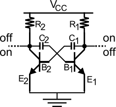
This is the last circuit proposed as working for an astable multi-vibrator.
It's now time to understand why this can or not correctly operate and if some issues are still present.

Due to the presence of R and C for each branch we're sure that the timing feature is somehow guaranteed; but how exactly is a matter we're going to see.

As already said at the switch-on one of bjts surely goes in saturation before the other which is so forced to go to interdiction.
We added the capacitors not only to make a timer as proposed but to alternates the states for the outputs too.

Let's suppose bjt2 wins the lottery and goes to saturation: its collector drops form Vcc to nearly 0.2V.
Due to the transitory nature of this falling signal, the capacitor won't block it at first instance so that it (the drop of  ~Vcc) will be replicated at its other top which connects directly to base1, the new value of which becomes:

newVb1 = Vb1 - ~Vcc

...continue reading "Astable – The completion"

Astable-First-look
Astable - First look

What essentially is an astable circuit useful for?
Just by thinking at its behaviour it can be considered a rudimentary timer with its two outputs alternating between on-off states and one each other in opposition.

First of all let's take again a first look to the circuit we saw in the previous post, here beside.

The links between the collectors and the positive supply Vcc up, and between emitters and ground down are dotted to indicate missing parts.
Suppose bjt1 on the right is interdicted while bjt2 is in saturation: if we connect both the collectors and emitters directly to the supply lines then the bjt1 would be charged quite entirely by the power supplier with the risk (depending by the bjt) to disrupt.

This suggests us to put a resistor in each branch: we choose between collectors and Vcc.

...continue reading "Astable – The parameters"

astable-howtothinkLet's start from the definition.
An astable (multi-vibrator) device is one unable to keep one state firmly but continuously oscillates between two states.

Up-down, one-zero, forth-back, all-nothing: whatever the way is in which you consider them the goal is the alternation between only two conditions.

By concentrating on the hardware we want to realize it: so where to start from?

High and low signals as referred to a ground one are furnished by every transistor and this means it's our first brick in the wall: let's say a very common one is enough for the purpose (for example the cheap BCxxx family bjts).

What kind of alternation is possible in output?
Not as the value of signals in itself but as the activation and control of the on-off.

...continue reading "Astable – How to think"

Valve Hack
Valve Hack

Buying from e-bay a common valve usually is not gravity feed.
Needs a lot of pressure in order to allow the water to flow when the coil is energized.
The tools that we are going to need in order to make this modification are :
A glue gun
A straw
A water bottle
Tape
A diode
A screw driver
A dremel with 1.7 mm drill bit
A 12V 1A AC to DC adapter / power supply

...continue reading "Converting a normal water valve into a gravity feed valve"

In this short post we will see how to do a measurement of resistance when you have to test a grounding system and how to do a ground resistance measurement.

**Little theoretical summary**

One of the major causes of injuries and danger in the electrical systems are high failure voltages (rated value of the system plus the power surge), due to generally high failure current (look at this post) of systems. Those currents are usually drained to ground by grounding systems. It's easy to understand why you want the lowest resistance possible in the grounding system, merely:

RG = UG / IF            (1)

...continue reading "How to do a soil/grounding system resistance measurement"