
What essentially is an astable circuit useful for?
Just by thinking at its behaviour it can be considered a rudimentary timer with its two outputs alternating between on-off states and one each other in opposition.
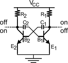
First of all let's take again a first look to the circuit we saw in the previous post, here beside.
The links between the collectors and the positive supply Vcc up, and between emitters and ground down are dotted to indicate missing parts.
Suppose bjt1 on the right is interdicted while bjt2 is in saturation: if we connect both the collectors and emitters directly to the supply lines then the bjt1 would be charged quite entirely by the power supplier with the risk (depending by the bjt) to disrupt.
This suggests us to put a resistor in each branch: we choose between collectors and Vcc.

Due to the previously highlighted temporal aspect of the circuit we need a system to guarantee it.
We have know resistors so the addition of capacitors is a must!
While the issue of power limitation is clear so that we know where to insert the resistors, the insertion of capacitors takes a little time more.
Indeed we could try the set-up as in the picture beside.
Where's the problem?
Always consider the working bjts: one in saturation while the other is interdiction.
Let's suppose that:
- both the capacitors are discharged, as possible at first instance;
- bjt1 in interdiction (and bjt2 in saturation).
Well... we have a contradiction: the voltage at the collector of an interdicted bjt is "high" so that we cannot have discharged capacitors; indeed they could be so before the insertion but after that they both immediately get charged and can be discharged in no way because are permanently bound to the Vcc through the resistor: neither the saturated bjt can be a discharging path for them.
So, how to get rid of it?
Again it's a matter of thinking about where the capacitors can be inserted without changing the nature of an astable.
Don't consider the capacitors for an instant and image to switch the circuit on (resistors don't affect it): maybe for a quick moment one bjt goes in saturation ("low" output) before the other but the equilibrium between the branches is rapidly reached with both outputs at Vcc.
Aha! it's time to exploit this asymmetry to keep the alternation on; and in few words asymmetry means activation of a bjt before the other, that is a base receives the "high" signal before the other.
We must intervene onto the bases.
As shown in the picture capacitors go between the collector and the base of the opposite bjts and now we're able to set the responding time of the branches (now C1 and C2 indicate the capacitors).
This is the winning circuit whose behaviour will be described next time.
Thank you for visiting us!
P.S.: are you sure this last configuration can work?