In this tutorial we will see how we can connect a RDIF reader into arduino.
We are going to use a 125 Khz RFID module that can be bought from seeedstudio.
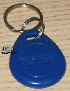
Some 125 Khz tags are also needed. We bought them from ebay but you can also find them on other online shops.
This guide is the first of a series of articles.
Starting from this article we are going to construct from scratch a home alarm based on arduino duemillanove.
Since the project is big we are not going to see a lot of details of each part / sensor.
In the future we will try to cover the theoretical gap.
These series of tutorials will be easy to understand and will help you to construct step by step the "A-H-A" (Arduino Home Alarm) project.
Radio-frequency identification is ideal for alarms since we can be identified via wireless.
More information about this technology can be found at wikipedia.
From seedstudio documentation page we can find the RFID Output Data Format :
- 0x02 - 1 byte start flag
- 10 ASCII Data Characters – Card number info - 10 bytes
- 2 ASCII Checksum Characters - 2 bytes
- 0x03 - 1 byte end flag
Notice that the 10 ascii characters represent a 5 byte key since two characters compose one byte.
The same is valid for the checksum. In this case the two chars compose one byte real value ("F""F" for example means FF).
If the 5 byte key seems too short for you remember that the possible combinations are (base)length .
In our case 5 bytes contain 5*8=40 bits.
The base is two and the length is 40.
So 240 = 1.099.511.627.776 key combinations !
Usually in the RFID tags the 10 ASCII data characters are provided.
An example is shown below :

The checksum can be calculated like this :
CHECKSUM = (Byte1_Card_Number_Info_Hex) XOR(Byte2_Card_Number_Info_Hex) XOR (Byte3_Card_Number_Info_Hex) XOR (Byte4_Card_Number_Info_Hex) XOR (Byte5_Card_Number_Info_Hex)
Again notice that the Byte1_Card_Number_Info_Hex is given by the first two chars of the 10 ascii data char string.
So now we know what we are going to receive by our reader. A 14 byte signal.
In the next page we are going to connect our RFID reader with the arduino board.
Notice that we are going to use the arduino 1.0.1 IDE version.