As i said i didn't got any good results by using IR led/photo diode.
So i will demonstrate the working way using the TOSHIBA Photocoupler TLP620−4 .
As we have seen at the photo diode article an opto isolator with photo−transistor is basically a ir led as emitter and a photo transistor as receiver. The photo transistor can be seen as a inversed biased photo-diode plus a normal transistor.
From the documentation we see that we have to connect the cathode of the ir led (emitter) to pin 64 and the anode into a 10K resistor and then to VDD (pin 48).
For the receiver (inverse biased diode) the anode goes to SERIAL PIN 2 (RXD) and the cathode into a resistor 220 ohm and the to serial 4 (DTR).
From the Toshiba opto coupler we get :

Here you can download the Toshiba data sheet : TOSHIBA Photocoupler
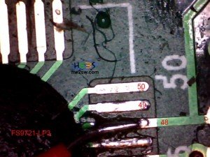
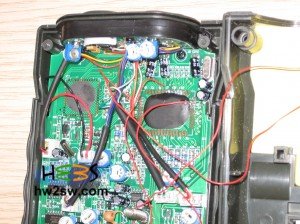
We start by soldering the pin 64 and the pin 48.

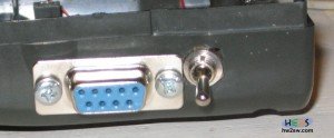
Now we place our DB9 connector. By doing this we can solder later the resistors and the opto coupler.
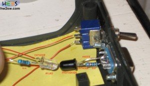
The connection of the opto coupler has been made with the dead bug technique. Notice that the opto coupler is upside down.

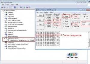
In order to test the circuit i have used SerialWatcher but you can use any serial listener.
From the page 14 of the IC documentation we understand that we should get a 14 bytes sequence like this :
1X 2X 3X 4X 5X 6X 7X 8X 9X AX BX CX DX EX
The connection was made using :
Port : your serial port . You can find it from Windows Device manager. [Start->Control panel->System->Device manager->Ports]
Data depth = 8
Stop bits = 1
No parity
Hard handshake = none
Sw handshake = none
Speed 2400 bps
Display Hexadecimal
If you get a sequence is correct you are done !
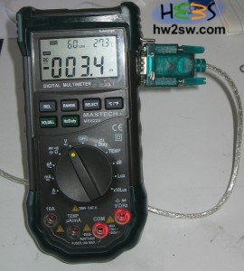
Some photos of the hole hack :



Update :
Christian Mauderer [we thank him] made some important observations :
If you look at the Wikipedia article for RS-232, you can easily find the correct Voltage levels for RS-232:
+3V to +15V as logic 0 or -3V to -15V as logic 1 for RxD.
The Range between -3V and +3V is not valid.
The levels for the control lines are inverted. (http://en.wikipedia.org/wiki/RS-232#Voltage_levels)
In my experience, +-12V are quite common.
If you use the circuit described in the data sheet of the FS9721, you will end up with one correct level (about +12V from DTR) and one floating level.
It is quite possible, that it works in most cases because either the serial port accepts the floating level as a low level (most likely because of internal pull-down-resistors).
Especially the USB-RS232-converters are quite forgiving in that issue.
But it is not mandatory that every port accepts the levels.
I think that Fortune semiconductors had that (and of course the additional costs of another resistor) in mind, when they designed their reference circuit.
On the other hand, the simplified schematic used by Voltcraft VC820 or VC840 can be found below seems much better, because they have correct low and high levels.
I think, that a mixture of both should be the best solution.
I have appended a schematic of the circuit, that I am using.
R3 (in my schematic) pulls the RxD-pin to a defined level, if the transistor of the optocoupler is switched off.
If it is switched on, the much smaller R2 is pulling RxD to the level of DTR.
At the same time R2 protects from short circuits (if something weird is connected to the RS232-connector).
Of course you have to set the RTS(serial pin 7) and DRT(serial pin 4) pins of the port to the correct levels.
RTS should have a low level (-12V) and DTR should have a high level (+12V).
As you can see, I have also changed the resistor between pin 48 of the IC and the diode of the optocoupler back to 1k.
The reason is that I am using a much slower optocoupler than you (I have recycled it from an old switching power supply).
Therefore I had problems with the edges of my signal: they were not steep enough.
The smaller resistor solved the problem.
In the next article we will talk about the decoding of that 14 bytes sequence and how we made a software application that does the data logging from this device.
Stay tuned !

