Let's start with a simple arduino project. A blinking led.  The digital pins of an Arduino have a maximum load rating of 40mA, so we do not want to exceed that. The voltage of the digital output pins are 5V.
So arduino digital output pins have these limitations :
An Imax=40mA and Vout=5V. The led needs up to 20mA maximum. So we can easily power it directly from arduino board.
From the Ohm's Law we have V=Iled*R => R = V/Iled = 5V/0.02A = 250 Ω. For security reasons we use a bigger resistor (330Ω) so that the Iled<Imax.
We have dimensioned our resistor, so now we are ready to test our circuit by constructing it on a breadboard. Remember to connect the ground pin and the 13th digital pin with your breadboard circuit.
Once you have made the prototype connect your USB cable on your arduino.

Run the Arduino GUI and press "Tools" and then board and select your board. Usually you will have an arduino UNO or an Arduino duemilanove.
From "Tools" - "Serial Port" select your USB COM port in order to communicate with arduino.
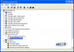
If you do not know which COM port you should choose, under Windows XP you can find it by doing :
Start -> Control panel -> System -> Hardware tab -> Device manager -> Ports (COM and LTP) -> USB Serial port (COMX)
As you can see in our case you have to use COM5 for the communication between PC and Arduino.
Now go to "File"->"Examples"->"Basics"->"Blink".
Once you have the code loaded press the "Verify" button. Once the code is verified press the "Upload" button.
You should see your led blinking every 1 second. Notice that arduino duemillanove has an embeded led too at the port 13 (Led L). In this case both leds should be blinking.
Below you can see the blinking code loaded on our Arduino.
/*
  Blink
  Turns on an LED on for one second, then off for one second, repeatedly.

  This example code is in the public domain.
 */

void setup() {
  // initialize the digital pin as an output.
  // Pin 13 has an LED connected on most Arduino boards:
  pinMode(13, OUTPUT);
}

void loop() {
  digitalWrite(13, HIGH);   // set the LED on
  delay(1000);              // wait for a second
  digitalWrite(13, LOW);    // set the LED off
  delay(1000);              // wait for a second
}
The arduino design has been made with fritzing. You can download the schematic from here : ArduinoBlink
Ok this is pretty neat stuff but what if we wanted to port this example into a standalone hardware project without using the Arduino board at all?