In the first two pages we have seen that a relay needs Io=5/70=70mA which is a lot of current for our arduino chip.
We have resolved the problem of back emf with the help of the diode placed at the pilot pins of the relay.
So in order to complete our mission we need to make an current amplifier in order to amplify a small current (from arduino) to a larger one that goes to relay. This has been discussed at the "common emmiter" article.
We have seen that we can get a DC current gain hFE=IC/IB where Ic is the collector current and the IB is the base current.
We are going to use a simple 2N2222 NPN transistor. Here is the datasheet : 2n2222
From the datasheet we can see that we have a hFE=β=75. Notice that from hFE we can see that the small current is located at the base Ib and the big curent is located at the collector IC.
Again from the datasheet we can see that the max IC = 800mA in DC so fits to our needs (70mA)
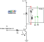
Now we have to place arduino digital pin at the base of the transistor and the relay at our collector.
The circuit diagram becomes

The only unknown factor at this point is RB.
Since we need 70mA at the relay we can set an Ic=100mA in order to be covered for the relay functionality.
We know that hFE=IC/IB => IB=IC/hFE=(0,1/75)mA=>IB=1,4mA
From the 1st Kirchhoff law we have :
Using Ohm's law we have RB=VRB/IB=(4,4/0,0014)Ohm=> RB=3142Ohm
So a RB=3K is ok for our needs.
Observe that a lower RB implies a lower power consumption and a higher IB so a higher Ic
It is showtime ! We have used the classic blink example from arduino demos.
We have used the digital pin 13 in order to pilot our relay.
When the light 13 is on then the relay is activated (+5V) else takes 0V.
void setup() {
  // initialize the digital pin as an output.
  // Pin 13 has an LED connected on most Arduino boards:
  pinMode(13, OUTPUT);
}

void loop() {
  digitalWrite(13, HIGH);   // set the LED on
  delay(1000);              // wait for a second
  digitalWrite(13, LOW);    // set the LED off
  delay(1000);              // wait for a second
}
We have constructed the circuit like the photo below

Here you can see the demonstrative video
Firstly you see the relay itself that switches on/off every 1 sec
Then you see the NC case (not in phase with the led) and lastly the NO case (in phase with the led).
All the dia diagrams can be downloaded from here : Relay Dia diagrams