We talk again of Serialino, our Arduino's clone: this time the printed circuit board (PCB) design is shown.
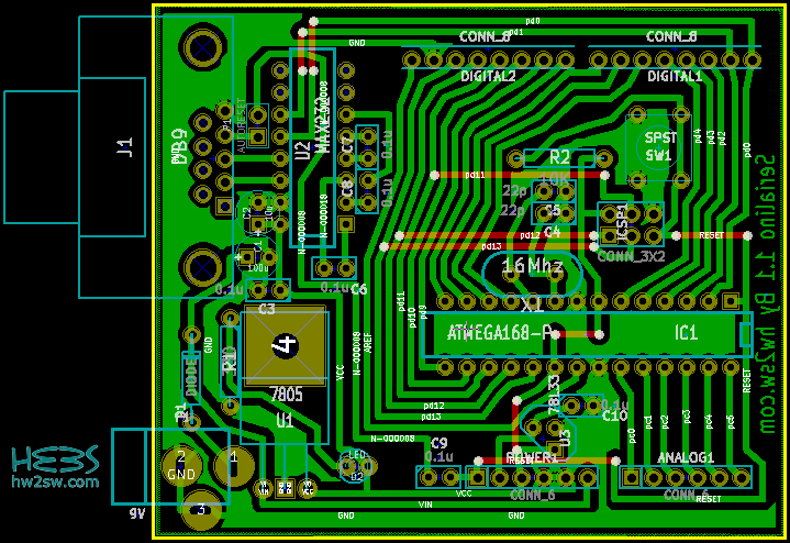
Here beside you find a screen-shot of the PCB of Serialino, numbered 1.0.
Even from here you should be able to distinguish the areas described in the previous post.
Power supply section on the bottom-left; the communication port and IC Max232 on the top-left; the headers on top and bottom; and finally ATMega with external oscillator, then the switch button and the ICSP pin headers.

You can also easily note the nine red lines which intersects some of the green ones; their presence is a direct consequence of the criteria in design; and we're going to explain why.
And indeed it's time to see how just three apparently simple criteria could constrict the designer to do a lot of work more.
We wrote the guidelines in the last article, which essentially are:
- low cost;
- easy to build at home;
- use of Max232 to communicate with pc through the serial port.
Let's begin from the less constraining point: the Max232.
Surely its sizes, especially related to a compact board, can be a problem: we must pay attention to the right place where to set it.
And indeed this is not so immediate, keeping in mind that lines will start from and will end into its pins.
But the first point, which involves the second one, shows the major difficulties: what does exactly mean low cost?
Because we want to produce the board at home, we need to minimize the physical job when possible.
In few words... Serialino has been designed to be single-sided.
The choice involves pros and cons.
While it will make the mask's printing a lot easier, we'll inevitably do some compromises.
But let's turn back to a very first step, the positioning of components.