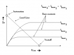
 As previously said, BJT's applications are typically as switcher or amplifier; switcher simply makes current flow or not - like light switch - and requires small reaction time, so that voltage goes from zero to max a value which gives a current matched on a curved line; and vice versa.
Amplifier mode needs Q-point lying on current curve when it becomes a ascending line, not curved.
In picture see three situations (from top to bottom): switcher, ambiguous, and amplifier.
Amplifying is possible only if Q-point stably stands on line, possibly in the middle.
Why?
Because this way we have the new voltage reference to make transistor work on signal variations: if we add to a AC voltage source input continuously moves up and down around
, and output voltage does same around Q-point.
By referring to graph, too big negative voltage leads transistor to switch off, while too big positive leads to over-current (not reported in graph) with a possible BJT burning.
Do you see now how Q-point's position is important?
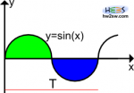
 With a small AC signal (an AC signal is an Alternate one, which in a period of T seconds repeats its value, having average value zero in T range, like sine and cosine functions - see picture) transistor shows a particular behavior, so called differential; this is a mathematical concept here interpretable as transistor's changes based on little input variations.
That's what we're talking about, little AC signals - variations - added to ; how does it influence BJT?
Depending by kind of study there are two basic models: 1) π; 2) Giacoletto's. Let's see the first, and only it.
Again... differentiation is a special type of division but thought for infinitesimal changes. So:
- between B and E we have a little current
based on little
or
, and their ratio gives a resistance
;
- between C and E we have a little current
controlled by
or
multiplied by correct coefficients (respectively
and
).
 Picture beside shows basic differential model, which reflects the two points above.
Pay attention to (we don't actually need
); it's the current gain in differential mode: based on AC signal's frequency, it usually differs from β (gain in DC or continuous signal - the biasing).
They almost match when variation is so small to be considered negligible.
To clarify, sometimes you can read , with capital FE: this is same as β.
What does or
stand for?!
- h for hybrid; transistor can be represented as a 4-ports-net model (with two matching), where respective voltages and currents are multiplied by h-hybrid parameters, which have resistance, conductance or no-one dimensional value;
- F and f -> forward (F for DC and f for AC);
- E and e -> emitter (same).
Too much to say about equations characterization, but this would become too much mathematical or technical.
Anyway i hope this very quick introduction could stimulate your curiosity, knowing that if you now get on hands a BJT's datasheet, like 2n2222, you're able to distinguish a NPN from a PNP, and you know what bias and differential gains are.
Thanks!
As always see you on next article!