As we said a reverse biased photo diode (called "photo conductor" ) when absorbs light drops it's resistance.
A video demonstration can be found below :
As you can see the IR Photo diode is connected to the multimeter reverse biased (the anode to the COM and the cathode to the +V of our multimeter).
Notice how the resistance drops when our Photo diode receives more light from the IR Led emitter.
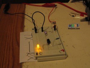
So we are now able to do a simple demonstrative circuit.
Notice that the IR photo diode is placed "inversed" biased.
More light is receiving from the emitter then less resistance has so the Led indicator light's up.
Less IR light is receiving from the emitter then has more resistance so the Led indicator turns off.

The dia diagram is located here : Testing IR Leds TX-RX
Again a simple video demo for this circuit is located below :
For further reading you should check :
electronics-tutorials.ws
hades.mech.northwestern.edu
me.umn.edu
Wikipedia Photodiode
Some pictures taken using a tripod without flash at low light and at no light in order to capture the IR LED light with our camera


That's all for now.
Soon we will see a real life application using IR receivers / transmitters.