What is a monostable?
And how can it relate to a timer IC?
As the word could suggest, it's something able to keep just one thing firmly.
For the NE555, or generally for a device, it must be intended as a condition itself.
But we know the name of the condition in jargon: state.
We talked about this concept introducing the S-R latch behavior indeed.
Well... in few words a monostable configuration simply means that 555 can keep stable only one between High and Low state. And to be precise the complete statement is monostable multi-vibrator.
Maybe what it has to be said is that in this case the output value matches with the state of the IC; but generally speaking these two concepts must be taken separately.
For our purpose we just consider them interchangeable.
Which of the two states does a 555 maintain?
The answer is bound to the electric scheme, which requires the 555 and a minimum of external components to set some parameters, all related to the timer function.
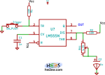
The above picture made in KiCAD shows a central block representing an LM555N, the CMOS version of 555, here without the pins 1 and 8.
By the description of pins functioning we can proceed connecting resistors and capacitors when needed.
First of all we find the input and output pins: here 2 (trigger) and 3 (output).
Then quickly: pin 5 (voltage control) is tied to ground but through a low-value capacitor (1nF) so that any DC (continuous) electrical value is filtered/blocked; in other words pin 5 doesn't see 0V but 2/3 Vcc still, just a bit more stable than without cap.
And obviously Vcc goes to pins 8 (power), and to pin 4 (reset) so that the IC cannot be reset.
Pins 6 and 7 remain, and there we add the external timing net with - in sequence - a first fixed resistor, a trimming potentiometer - or variable resistor - and a capacitor at the end, tied to ground.
As you may know resistors and capacitors have entities, resistance R and capacitance C, which result in time value when multiplied.
Yes: ohm * Farad = second!
Simply the capacitor accumulates or loses electrical charges, and it does so through at least one resistor.
Accumulation and discharge require time, and this last is translated into voltage or current by resistor and capacitor together.
As you can appreciate from the scheme, the charging phase is automatic with the circuit powered.
How to invert this and make the discharge start?
Surely we need to make the capacitor discharge itself, and if you remember the pin 7 is named discharge. It has been designed for the goal; ok, but how to use it?