When scheme is complete, next step is to check the electrical nodes working; Kicad needs to create a map (known as NetList), which can contain any kind of circuit information, independently by its effective correctness.

 Next step would be creation of NetList; but we want a working scheme, so before we proceed with the ERC (Electric Rules Check) process: in order to get it, it's necessary to give each component a unique name.
A quick way is clicking on icon-button as in left picture (Annotate schematic), on "Annotation" button (right picture) without changing anything, clicking OK on warning message; finally you get your circuit with all components renamed.

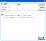
 Now it's time for ERC: so watch picture beside. Press that button (Perform electric rules check) to get a new operating window where to launch the job from.
Because of some possible bugs Kicad could show some strange errors, especially bound to grounds. Not so important, indeed: but it's vital to know it, to avoid wasting time to correct an error that simply doesn't exist.

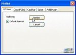
 Lastly the Netlist creation: click on "Generate netlist" icon-button to get a dialog window (respectively left and right picture); click on Netlist button taking care of keeping every voice untouched.
Kicad now creates this important map to be reused directly in PCB working space: it will ask you to save the .net file.

 To complete this first part we proceed assigning our favourite footprints to components.
Run Cvpcb and in next window assign one kind of footprint (right) to the selected component (left).
If you don't know the meaning of footprints list voices then use 2D and 3D views: click the icon as on above second picture (View selected footprint) to get the 2D view as on beside first pic; form this window click on red 3D icon to see the movable model (hold mouse clicked and move it).
Don't forget to assign footprints to each components, otherwise you'll get an incomplete unusable netlist.
Following video shows you how to do.
Now it's time for second part. Let's go!

