We have all basic instruments to do the job.
First of all set the grid to 5 mils, good resolution to design; in facts confronting with original relay_2rt (you can load it into EESchema to have a model) and setting the resolution to the above one, you'll see the correct distances and lengths.
 First the rectangle of inductor: you can indifferently use the forth or the seventh palette icon; usually with a rectangle you delimit the symbolic component body, but it's not a rigid rule.
Being close to model we trace 10 steps horizontally and 40 vertically.
Little trick 1: click on a point with your tool selected and then move with keyboard's arrows.
Little trick 2: to get a crossed reference, choose last icon on left palette (Change cursor shape).
Choosing the forth you simply click-drop-click; with the seventh click-drop-doubleclick.

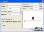
 Click on the second to add pins; on first picture beside only pin number is set.
Press OK and put it where you want; or the pin-8 eight steps down from rectangle's top and eight left, while pin-9 twelve from bottom and eight left.
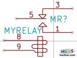
Result must be like beside.
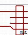
Remaining job is intuitive and simple; just use line or arc tools where needed.
Note that arcs are designed while original model has 3 lines; not so important, as previously said.
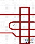
Following pictures show how to complete the inductor's symbol.

 Inductor's symbol is complete; let's start with the switching part.
Triangles and lines are now simple draw; after add new 3 pins: number 5 as previous ones, 1 and 3 are little different, just for their left orientation instead of right.
Final job must be like on right picture.


