Skip to content

Serialino-PCB
Serialino - PCB

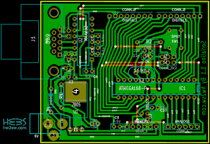
We talk again of Serialino, our Arduino's clone: this time the printed circuit board (PCB) design is shown.
Here beside you find a screen-shot of the PCB of Serialino, numbered 1.0.

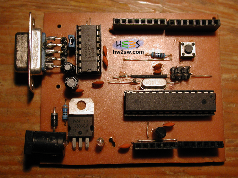
Even from here you should be able to distinguish the areas described in the previous post.

Power supply section on the bottom-left; the communication port and IC Max232 on the top-left; the headers on top and bottom; and finally ATMega with external oscillator, then the switch button and the ICSP pin headers.

...continue reading "Serialino – The PCB"

Serialino-top
Serialino - Top

Last time we talked about the importance of prototyping, when you decide to develop an idea involving electronics; this is worth especially if everything is direct to get the final result into a copper board.

The better the prototyping, the more efficient the copper board.

You know that the signal's integrity on breadboard is affected but multiple sources of noise: the capacitances and resistances due to the internal paths are just a little example, being negligible for standard circuits in DC or low frequencies power supplying.


Nonetheless you may want to know about it.

...continue reading "Serialino – Presentation"

Every package of software suite comes with an amount of collateral applications, extensions and/or libraries.
KiCad does the same; but sometimes default components aren't enough for specific goals.

Thanks to KiCad's popularity people around the world spent some of their time to enrich the base: so that you can find useful libraries or scheme directly for free on websites. Here some of them (in my opinion the most important):

Now think you don't find component you need among default and external or third-part libraries.
Two main solutions show to yourself:

  1. desperation, with profession abandon or change;
  2. design your own.

...continue reading "Kicad. From Software To Hardware Part3"

1

Toner transfer method

The toner transfer method is one of the most common and cheap way to make Printed Circuit Boards at home.
Despite it's popularity this method has problems with it's repeatability since it has way too much factors that must be cleared in order to get some decent and stable results.
The method itself is pretty straight forward.
Print your circuit with your laser printer then put the printed circuit face down over a copper clad so that the toner touches the copper surface and then apply heat in order to transfer the toner from the paper to the copper.
Then you remove with water the paper and the toner will be printed into the copper clad.
Now you are ready to etch the board.
Then drill place the parts and solder.

...continue reading "How to make PCBs at home – The toner transfer method"

The hacked laminator

Generally you need heat in order to accomplish the toner transfer method.
The toner transfer method will be explained in later tutorial.
The most difficult part at the toner transfer method is exactly this ! The toner transfer from the printed paper to the copper clad.
The classic method is to use a hot iron and iron your copper clad with the printed circuit over it.
Trust me, this method is hopeless. Even if you get a decent result you can not repeat it again and again.
You will only have a small percentage of success.
The paper , sure, is a key to this problem but does not solve all the mystery about this method.
The main problem is that you need to heat up the toner while you keep pressing over the paper.
So you have to do two things in the same time with the hot iron.
Instead doing that it is more convenient to buy a regular laminator at your local store and modify it a little bit.

...continue reading "Turn a common laminator into a PCB laminator"